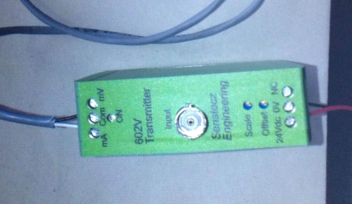
Ultra-High Impedance Isolated Transmitter
Model: 602V – Ultra High Impedance Measurement
Application
SENSETECZ 602V transmitter is used for ultra high impedance measurement by monitoring the floating voltage from multi-isolated channels or sources – among which there is no electrical connection. No load will be applied and no current will be injected to the sources to be measured. 602V has either voltage output or current output: output -3VDC to +3VDC correspond to input signals 3V to +3V or 4-20mA corresponds to input signals -2V to +2V. It scales -2V to +2V voltages into 4 to 20mA currents which enable the module directly connect to the DCS or PLC system in the plant.
Features
- 602V transmitter measures the voltage with a voltage follower which has ultra-high input impedance (larger than 5×10¹² Ohm) and ultra-low bias current (less than 10-13 A). No load will be applied and no current will be injected to the sources to be measured by 602V voltage follower.
- An isolation amplifier isolates the input from the rest circuit. It allows 602V to measure the floating voltages from multi-isolated channels or sources – among which there is no electrical connection.
- A 4-20mA transmitter circuit scales -2V to +2V voltages into 4 to 20mA currents. Thus the module can directly connect to the DCS or PLC system in the plant.
- EMC/EMI design is applied on 602V. ESD protection and RF filtering circuits have been added to all the ports, including Signal Input, Output and Power Inputs. 602V is designed to measure voltages in the industrial environment where measured sources have high impedance but low current leakage is required.
- Intrinsic design is applied to 602V. The maximum current has been limited by the passive resistors to the safety level which makes 602V be suitable in fire hazard environmental application, such as in chemical process plants, etc.
Working Principle
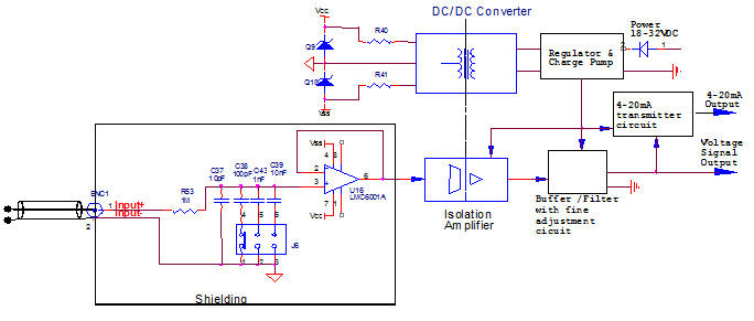
Simplified Schematic
Voltage Follower
The voltage follower uses the same operational amplifier IC (LMC6041) which has been used and approved successfully for the last 10 years in SENSETECZ electrometer design. The operational amplifier provides:
- Ultra-high input impedance, guaranteed larger than 1T ohm. IC is tested before assembling, actual value larger than 10T
- Ultra-Low Bias, less than 2fA. IC bias is tested, passing criteria: 2fA or lower
- 2KV ESD protection
Combined the high performance of LMC6041 with the following characteristics, SENSETECZ designed 602V’s voltage follower.
- The follower and input circuit are shielded in a metal box completely, which will remove the interference of external electrical charges.
- The input pin of the operational amplifier is lifted away from the PC board to avoid the interference of the board leakage.
- High dielectric potting compound is used to seal the input circuit to reduce the interference of humidity.
- With the fully shielding of the input circuit, low capacitance capacitors can be selected for input low pass filter. The larger the capacitance, the less fluctuation the input will be. On the other hand, larger AC leakage will be caused to the source. With the fully shielding of the input voltage follower, very low capacitance can be selected for lower AC leakage but clean output signals (High Signal to Noise Ratio) can be achieved at the same time.
For example, if the source has 1 Hz AC signal, the impedance of 10pF capacitor will be 1.59×10¹⁰ Ohm. This will cause certain amount of AC leakage current.
SENSETECZ recommends that the selected capacitance shall be 10 times less than the capacitance of the source to be measured.
The input capacitor of 602V can be selected via a jumper on site by the customer or can be set by the supplier before shipping based upon the customer’s requirement from 10pF to 10nF.
Isolation Amplifier
The isolation amplifier has very low temperature drift, high linearity and automotive operation temperature. The signal amplitude from the output of the voltage follower restores here and the differential output signals of it inject to next circuit.
4-20mA transmitter
A set of potentiometers are used for “Offset” and “Gain” adjustment. .
Input signal of -2V to +2V will be shifted to 0.5 to 2.5V. A standard high precision 4-20mA transmitter is constructed by combining IC and high precision (0.1%) / low drift (10PPM/°C) resistors, MOSFET and Capacitors. The output of this transmitter is protected with diodes (reverse protection) and TVS (ESD).
Power Supply
Linear regulators provide constant voltage to amplifiers and DC/DC convertor
A charge pump provides -5V
An isolated DC/DC convertor provides isolated power supply to the follower
The input of the power supply is protected by diodes (reverse protection), PTC reset fuses (current limit) and TVS (ESD). An inductor is used for RF filtering.
SPECIFICATION
- Input impedance: > 5T (5×10¹²) Ohm@25°C; > 1T(1×10¹²) Ohm@60°C
- Bias current: < 10fA @25°C to the input electrodes; < 100fA@60°C to the input electrodes
- Isolation: 1500Vrms between the input, output ports and power supply
- Accuracy: ± 0.025% Max
- Output: -3VDC to +3VDC correspond to input signals -3V to +3V; or 4-20mA correspond to input signals -2V to +2V
- Noise: < 0.5mVrms with 250 Ohm loop resistance
- Response time: <50mS reach 98% of final signals
- Drift: 10µV/˚C
- Power supply: Single power supply any value from +18VDC to +30VDC
- 4-20mA loop resistance: 50 Ohm to 500 Ohm
- EMC/EMI design: IEC61000-4 compliance
- Power consumption: 70mA with 4-20mA circuit; 50mA without 4-20mA circuit
- Operation Temperature: -10˚C to 60˚C
- MTBF: > 175,000 Hours
- Intrinsic safe design: Compliant to fire hazard environment and electrical safety
- Humidity: 0-95%RH
- Warm-up time: no need
- Dimension: 79.5mmLx20mmWx70mmH, Phoenix DIN enclosure
- Weight: 150g